In today’s realities, the concept of safety at home has acquired special importance. For many years now, every AVR Development project has necessarily included a built-in shelter or refuge to protect residents and visitors from military threats or natural disasters—right within their own homes.
The optimal planning solution for protective structures in residential buildings is the combination of a built-in parking facility and a protective shelter, with access routes that do not expose occupants to danger. When designing such dual-purpose structures, engineers face challenges in ensuring impact resistance and structural stability, as well as maintaining a comfortable and safe indoor microclimate.
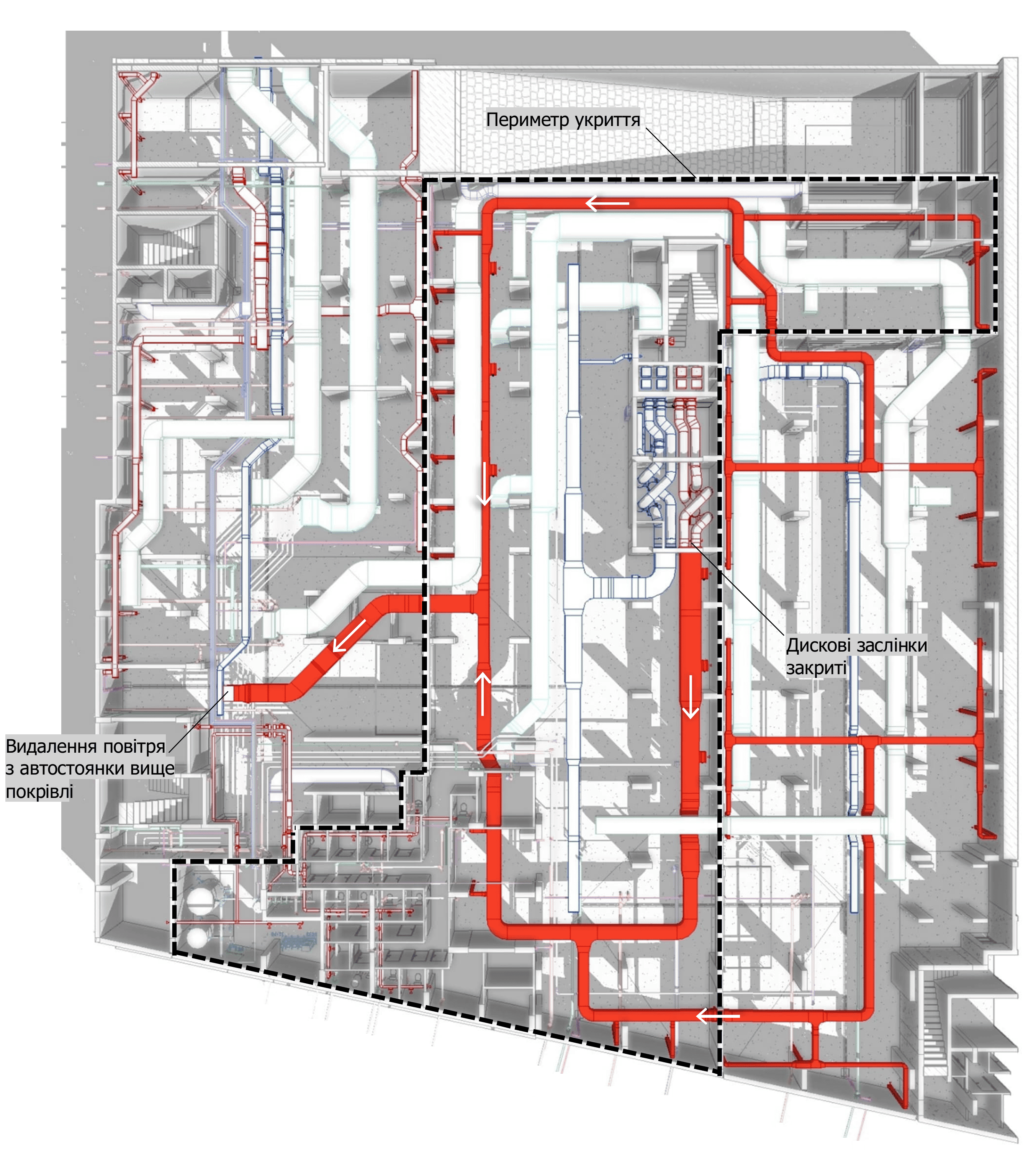
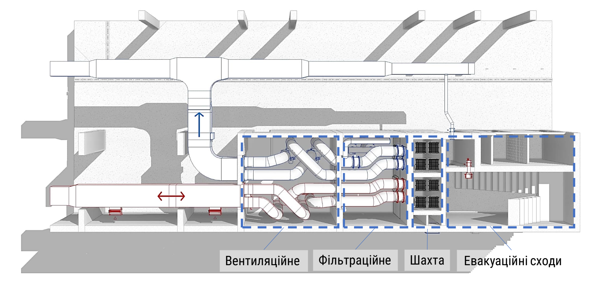
In large residential or multifunctional complexes, built-in underground parking facilities are usually extensive in both capacity and area. Consequently, they require long and branched duct systems for ventilation, which increases construction costs and complicates the installation of the complex’s engineering systems. Moreover, in parking areas with protective shelter functions, the situation becomes even more complex due to the need for an additional emergency ventilation system powered by autonomous fans with an independent duct network. This combination leads to an overconcentration of intertwined utilities (Fig. 1), some of which are only used in emergency operation scenarios.
Fig. 1
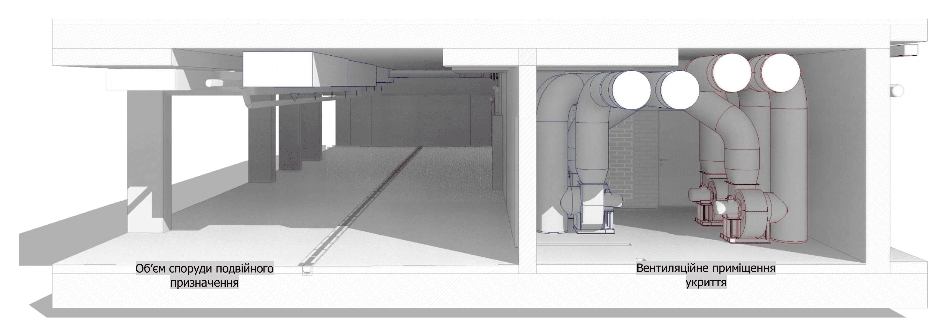
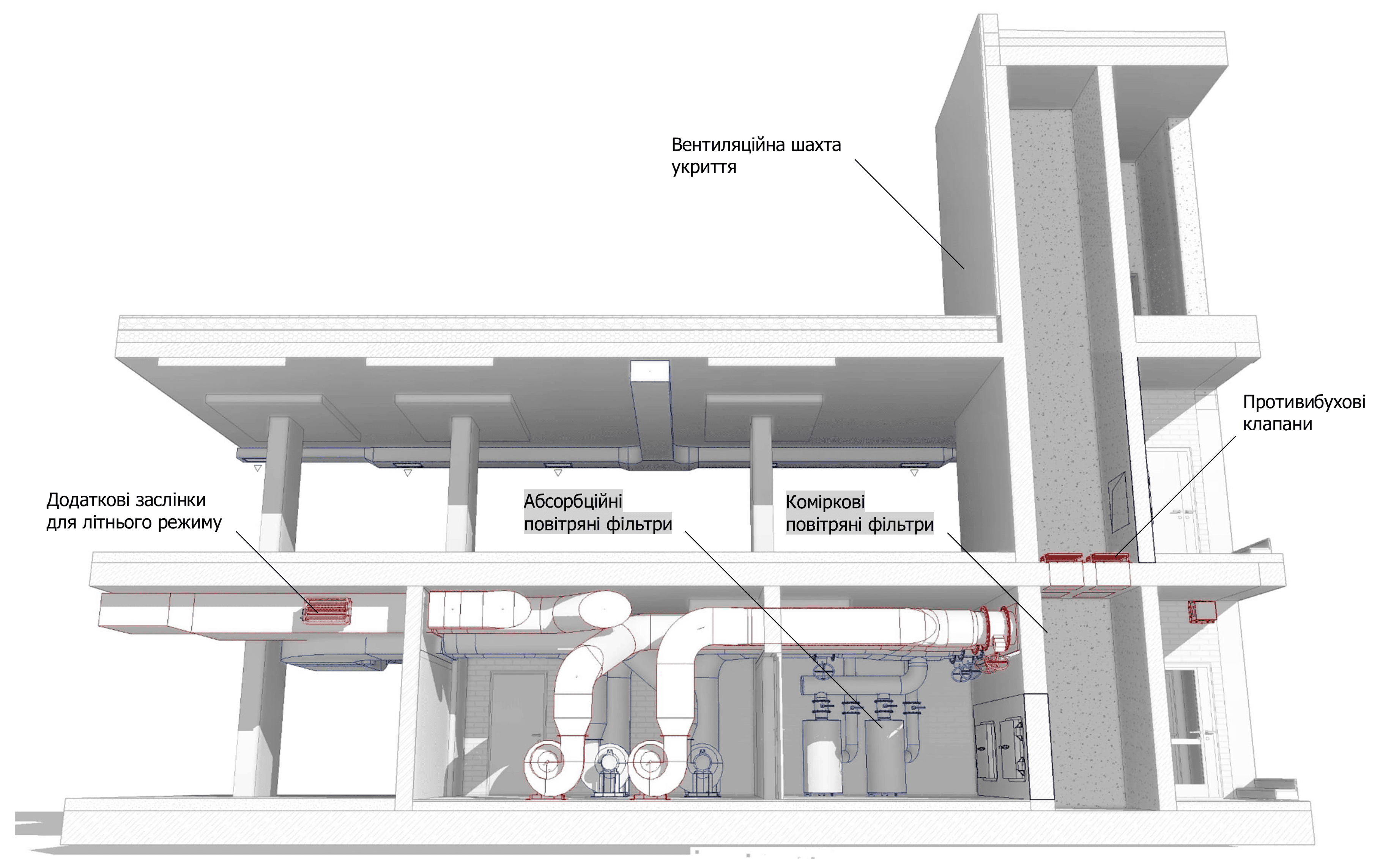
The AVR Development team continuously improves its approach in pursuit of the most optimal and resource-efficient engineering solutions. One such innovation is the integration of the parking ventilation network with the protective ventilation system of the shelter (Fig. 2).
Fig. 2
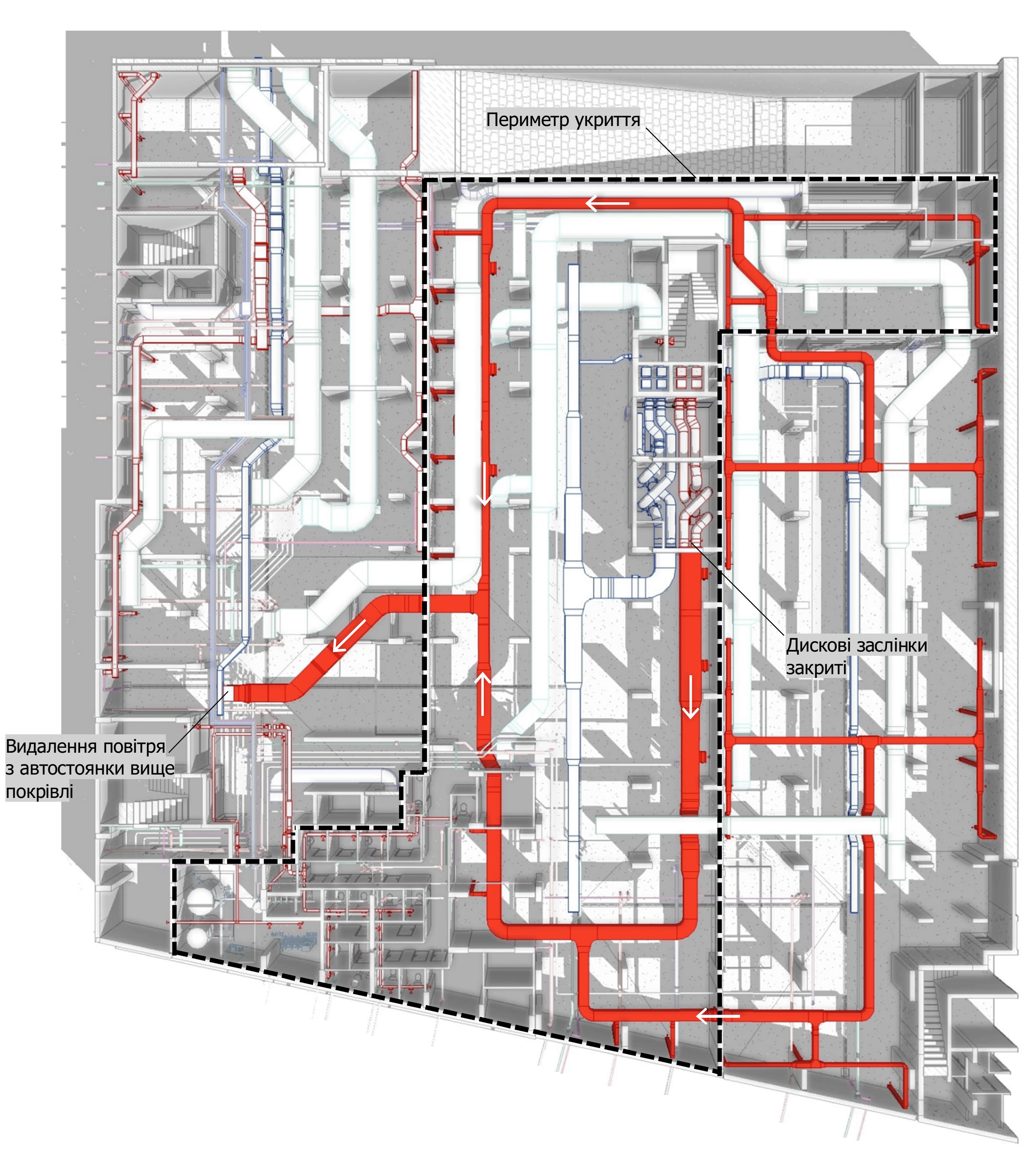
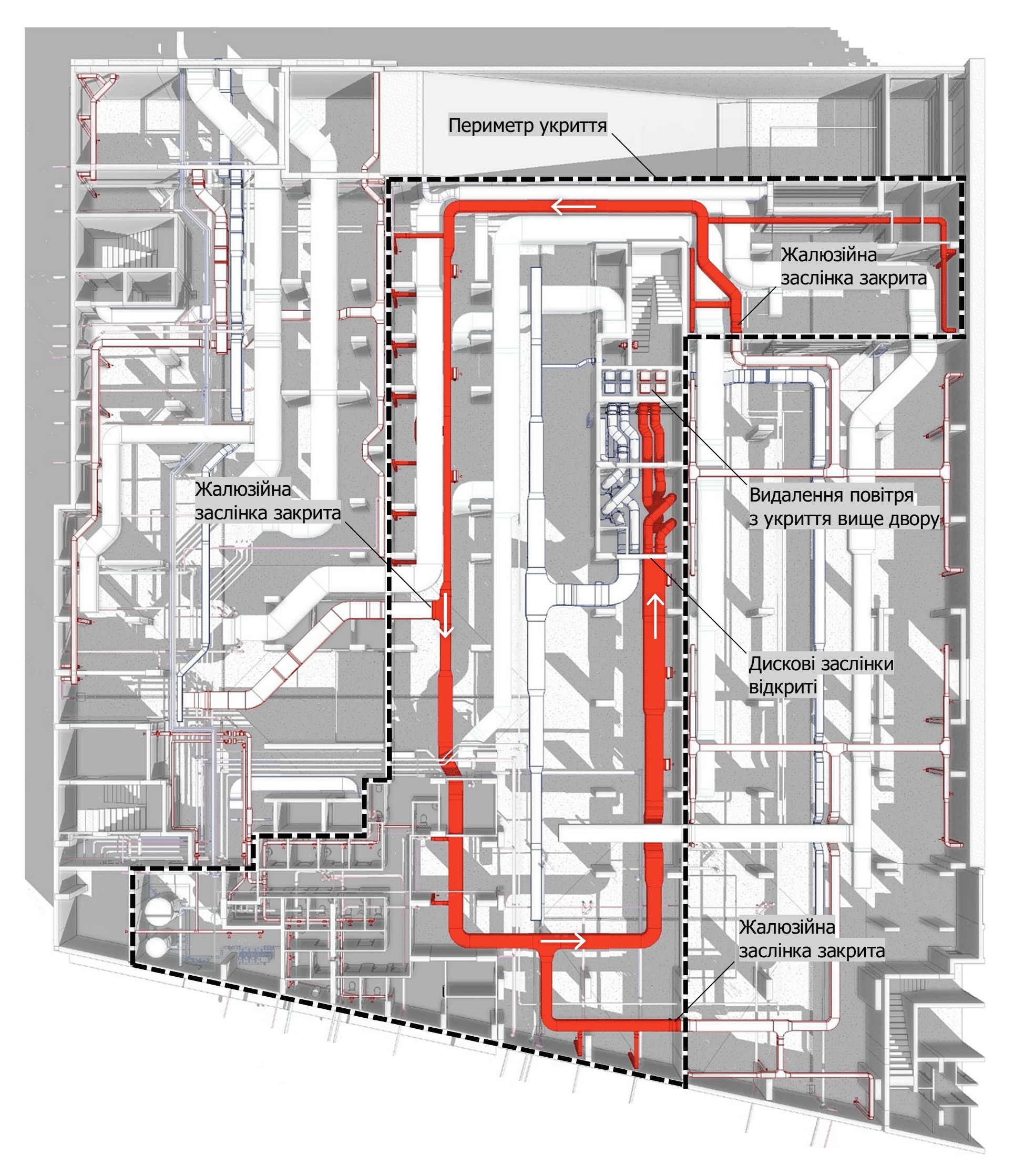
The network of ventilation ducts serves as a transport corridor for expelling either polluted air—contaminated by vehicle engine emissions—above the building’s roof (Fig. 1), or relatively clean air during shelter mode operation (Fig. 3) to a zone protected from destruction. Through remotely controlled dampers installed on branches of this corridor, the automation system redirects airflows from standby fans to emergency ones (Fig. 4).
This way, the core part of the ventilation network is utilized across the maximum number of operational scenarios for the dual-purpose facility, significantly reducing idle sections of the system.
Fig. 1
Fig. 3
Fig. 4
A large building complex requires the shelter to accommodate a significant number of people, which means the ventilation networks must be sizable—especially the air intake and exhaust shafts that extend to the surface. To ensure the necessary dimensions and guarantee the protection of these structural elements from destruction, we construct durable reinforced concrete shafts with built-in protective dampers that absorb the pressure of blast waves on the shelter’s ventilation systems, along with sealed protective hatches that allow service access (Fig. 5).
For efficient use of space and materials, these shafts are often integrated with the walls of evacuation tunnels or stairwells leading from the shelter to a zone safe for people.
Fig. 5
The high density of utility networks and limited space for their installation demand well-thought-out design approaches and further cost optimization—something AVR Development engineers know how to handle best. With each completed project, we gain invaluable experience, and our solutions become more resilient and refined to meet new engineering challenges.
Prepared by HVAC engineer Oleksandr Shynkovych

